Data links
for drones
and robotics
Smart functions
and technologies right now
3D Link
Bi-directional
DATA LINK FOR DRONES
AND ROBOTICS

and TELEMETRY CHANNELS
IN ONE DEVICE

line-of-sight (LOS) range

AND MULTIPLE DRONES LINKS

3D Link HP
HIGH POWER
BI-DIRECTIONAL
DATA LINK
FOR DRONES
AND ROBOTICS
and TELEMETRY CHANNELS
IN ONE DEVICE
LINE-OF-SIGHT RANGE
AND MULTIPLE DRONES LINKS
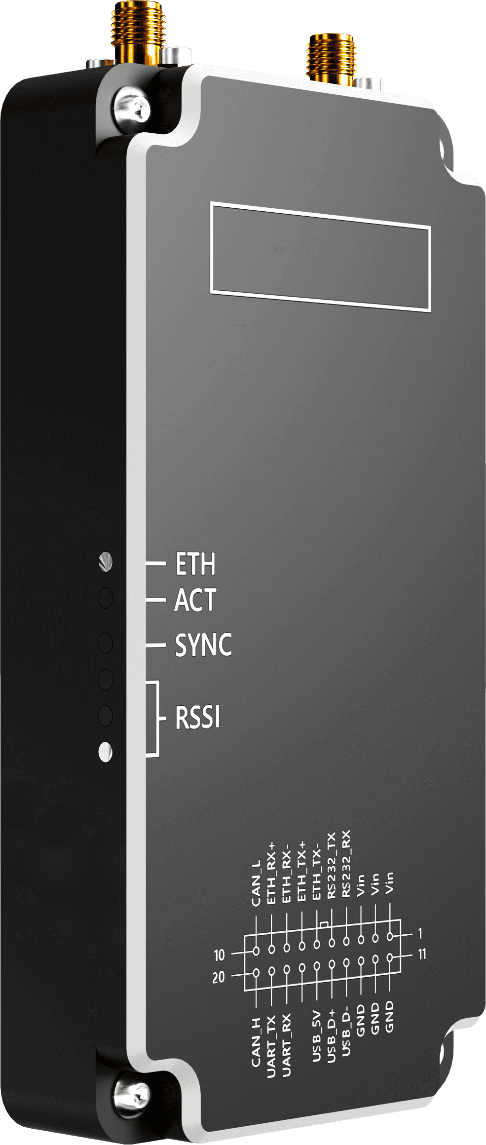
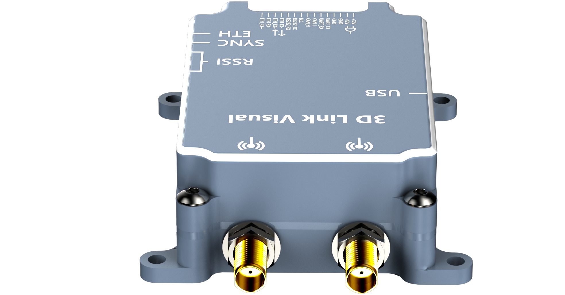
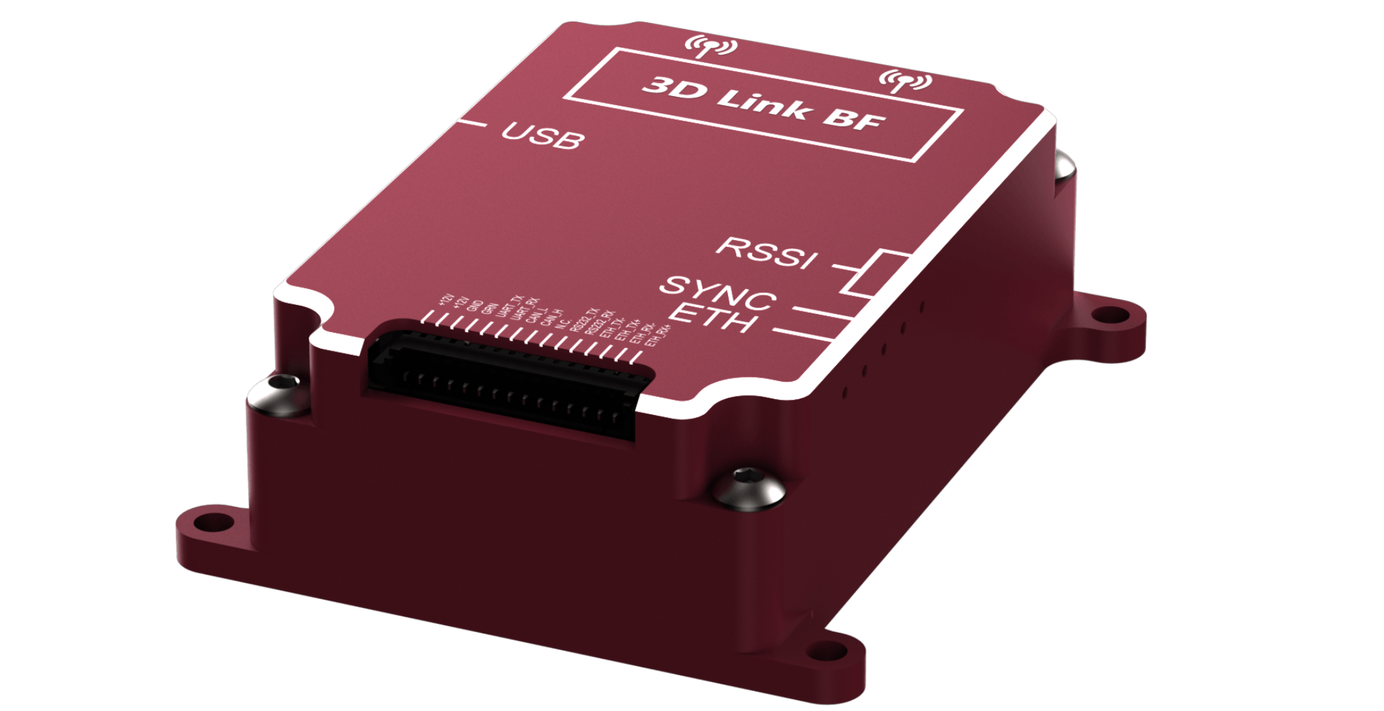
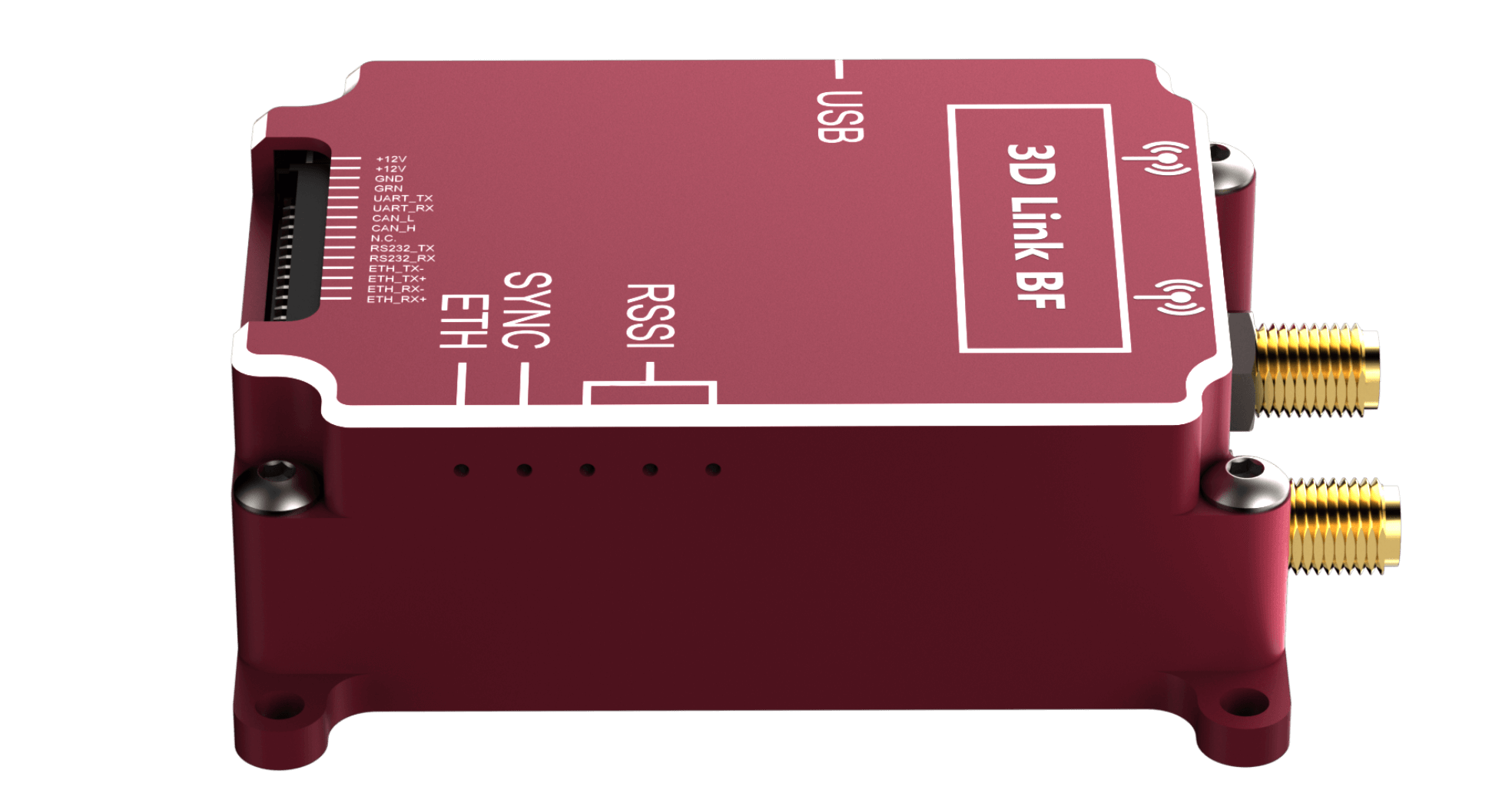
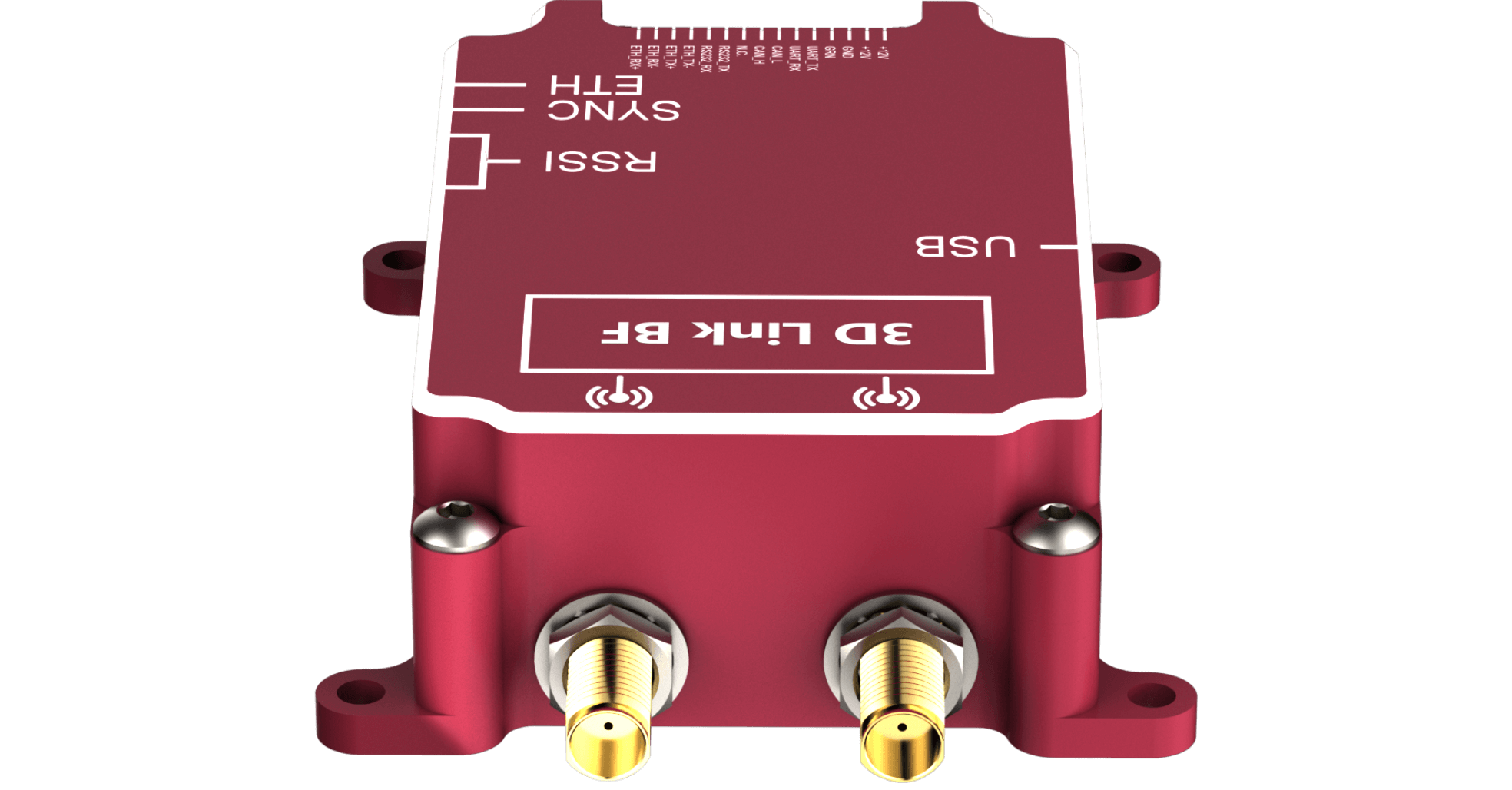
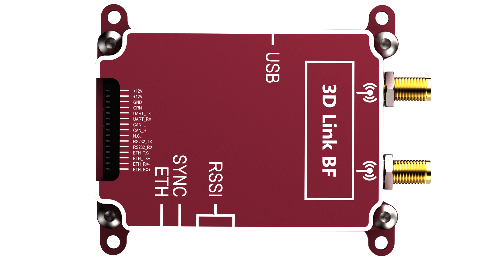
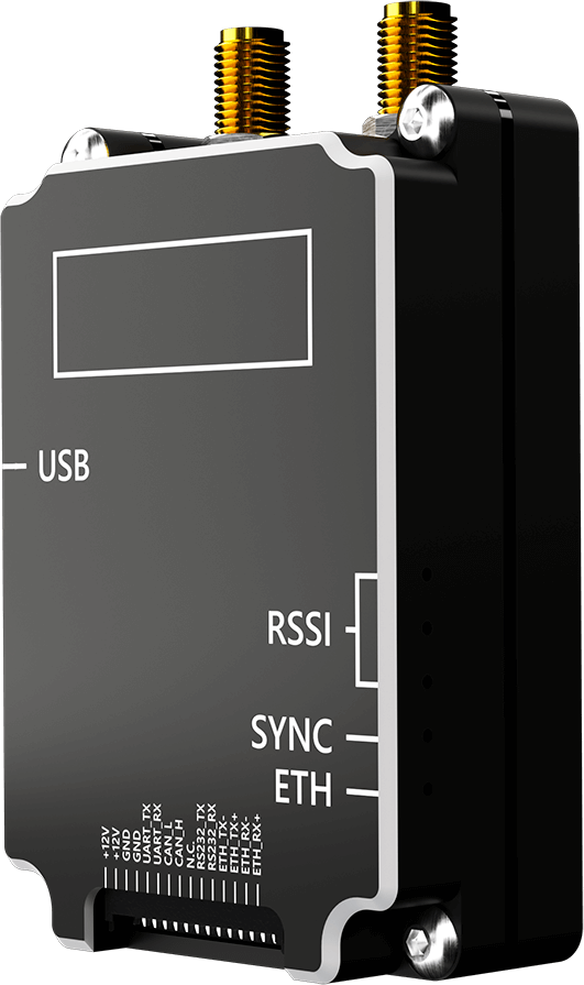
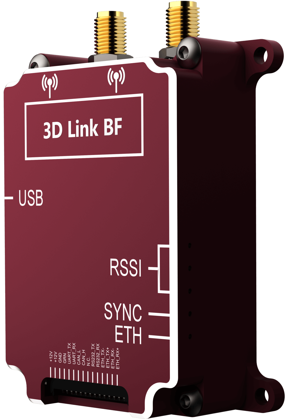
3D Link BF
BI-DIRECTIONAL DATA LINK
FOR DRONES AND ROBOTICS
WITH INCREASED RANGE AND
ANTI-JAMMING CAPABILITY
and TELEMETRY CHANNELS
IN ONE DEVICE
LINE-OF-SIGHT (LOS) RANGE
AND MULTIPLE DRONES LINKS

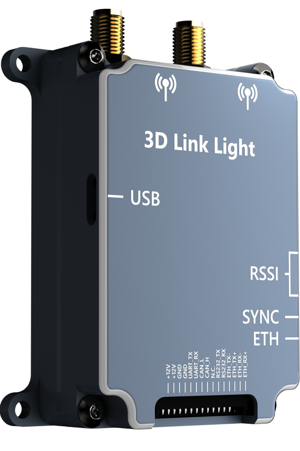
3D Link Light
LOW-COST
BI-DIRECTIONAL VLOS DATA LINK
FOR DRONES AND ROBOTICS
and TELEMETRY CHANNELS
IN ONE DEVICE
AND MULTIPLE DRONES LINKS
KEY FEATURES
OF 3D LINK
Retransmitting mode

HIGH-SPEED, CONTROL
and TELEMETRY CHANNELS IN ONE DEVICE

Network

Non-line-of-sight operating

ABOUT
COMPANY
The UAV radio’s mission is to bring our customers the highest possible performance wireless links for UAVs, unmanned ground and marine robotics for a reasonable price.
In 2008 we started to use the adapted WiMAX technology based on our IP cores in the field of wireless communications with robotics. The result was good but not the best. Communication with robotics is highly specific, and off-the-shelf wireless technologies like WiMAX, Wi-Fi or DVB-T may be not optimal at all even if adapted. A new wireless technology designed especially for robot needs is required. In 2013 we started the R&D project aimed at the creation of that brand new proprietary technology. The first field tests were made in 2016 with impressive results. Since that time we have made many corrections and improvements to bring proven solutions based on that technology to the market. Now we are proud to offer them to our customers.
UAV radio uses the best world practices in R&D, manufacturing and deployment of our products. Making equipment for a robust robot wireless link is a hard task but making this equipment to work well on a specific robot is hard as well. The UAV radio’s philosophy is never to leave our customers with the second task face to face alone. We always participate in the deployment process of our products and do it well. Another important UAV Radio’s concept is that all our equipment was designed with an aim at easy integration. We would like our customers to spend their time on creativity in robotics and not on debugging of-the-shelf radios. But the best prove of all our concepts and endeavors is that UAV Radio has dozens of successful cases of our equipment installations on UAVs, unmanned ground and marine robotics, and dozens happy customers around the world.
Technologies
UAV Radio unveils an unique hybrid of
OFDM and spread spectrum communication technologies
Following our endeavor to make the best possible wireless links for robots UAV Radio developed the fully original PHY level specification of OFDM technology OFDM_Flexi. OFDM_Flexi organically comprises a high-speed and spread spectrum (SS) data transmission within the framework of the proven OFDM technology.
For the control and telemetry channel OFDM_Flexi uses the original SS technology where each bit of information is maximally spreaded over the entire signal bandwidth of the OFDM signal by a properly concatenation of a LDPC error correction code and a code with repetition of bits. It gives to the channel an excellent immunity to the receiver noise and channel distortions, anti-jam and low probability of intercept (LPI) features that are very desirable for mission critical applications. The figure below shows the spectra of the OFDM_Flexi signal in SS mode together with the receiver's noise spectra and the narrow-band interference spectra.

Note that the spectras of receiver's noise and interference can dominate over OFDM_Flexi spectra in SS mode down to −17 dB. So SS mode of OFDM_Flexi technology permits a substantially negative in dB signal-to-noise ratio (SNR). This technology of concatenation used in OFDM_Flexi is unreachable for virtually all OFDM wireless technologies based on open standards and many proprietary due to an autocorrelation method of a signal detection used in them. The autocorrelation detector is cheap in implementation, but it does not work for SNRs that a little less than 0 dB. On contrary OFDM_Flexi uses a matched filter detector with an exhaustive search over a frequency-time plane. It is hard in implementation, but it gives an unsurpassed robustness to the control/telemetry channel. Also a negative in dB threshold SNR means that the OFDM_Flexi SS waveform is hard to intercept without a knowledge of signal structure because the signal is deeply buried into a noise. It is absolutely not the case for wireless technologies based on the open standards. Their waveforms can be relative easily intercepted and decoded due to a open standard specification. Note also that users can take some control over the OFDM_Flexi waveform structure via our SDR_Surfer application so that the modems of different users will not be able to decode waveforms of each other.
For the link synchronization OFDM_Flexi uses a sophisticated matched filter detector with a exhaustive search over a frequency-time plane. It gives an ability to support the link synchronization for input signal-to-noise ratios (SNR) down to −17 dB. This performance is unreachable for virtually all OFDM wireless technologies based on open standards and many proprietary too. As a result OFDM_Flexi can maintain robust link synchronization in conditions when many other wireless technologies fail.
The high-speed mode of OFDM_Flexi is based on the OFDM technology with superior performance supporting data rates up to 64 Mbps. This mode is perfect for digital video and Ethernet traffic from robot to the ground station (GS). The figure below shows a spectra of the OFDM_Flexi signal in high-speed mode together with the receiver's noise spectra and the narrow-band interference spectra.

Note that to transfer data at high speeds needs the high SNR with respect to the receiver noise. As shown in the figure the OFDM_Flexi signal spectra in high-speed mode must substantially dominate over the receiver noise spectra but not over the interference spectra if present. This is because all UAV Radio's receivers are equipped with the narrow-band interference rejection filters. So the the high-speed OFDM_Flexi channel needs a positive in dB SNR with respect to the receiver noise only. However, the need for the positive SNR makes the high-speed channel moderate to highly vulnerable to noise and makes it the channel with a moderate to high probability of intercept. It is not the problem if the end of the high-speed link resides at the GS where highly directed antennas can be used. But to use the high-speed channel also for transmission of the control and telemetry information as do many off-the-shelf links based on the open wireless standards is a bad idea especially for the control (GS→robot) channel.
The figure below shows typical implementation scenario of OFDM_Flexi technology to the UAV-GS communication in the form of a time division duplex (TDD) frame for waveform with a 12 MHz bandwidth.

It follows from the figure that the control/telemetry channel has a high robustness due to the SS waveform with a low threshold SNR of −4 dB. Aggregate rate of 256 kbps of the channel is quite enough for almost all UAV autopilots and the speed can be adjusted as desired. The UAV-to-GS link is on the contrary high-speed with 7.5 Mbps rate. It is more than enough for a HD video and the rate also can be adjusted. Note that UAV Radio's GS→UAV and UAV→GS channels can work on different carriers. This feature gives to the link an extra anti-jam performance very desirable in mission critical applications. Really, an interceptor in the place of UAV activity sees only signal at F1 frequency because signal at F0 is too low due to a large distance between GS and UAV and due to the LPI feature of SS mode. If there is no signal at F0 therefore the jammer at this frequency is not settled with a high probability. So the GS→UAV channel will be not corrupted by jammer also with a high probability. Highly likely that the jammer will be set at F1 frequency because the signal at that frequency is radiated by the UAV and has an relatively large level at the jammer place. But setting the jammer at F1 may be ineffective due to a large distance to the GS where the receiver of the GS→UAV link resides.
Adaptive antenna technology in UAV Radio's products
Most robotics now are equipped by omni-directional antennas. Omni-directional antennas have many advantages such as small form factor, low weight and cost, convenience in use, lack of an antenna tracking system and these features are in high esteem by robot designers. But omni-directivity has its dark sides which are as follows.
1. Omni-directional antenna radiates energy very inefficiently ― only small part is radiated in a receiver direction, most part of energy is wasted. It is a disaster for a video channel from robot to a ground station where a lot of information is transferred and as a sequence total energy losses are enormous.
2. Omni-directional antenna receives energy inefficiently as well ― it adds together signals from all directions with equal weights, so it does not separate useful signal from interference and if interference signal is on the same frequency as useful signal the quality of link can deteriorate dramatically.
Counterpart of omni-directional antenna is a directional antenna with no drawbacks of omni-directional one. But hardwired directional antennas need mechanical tracking system that may be prohibitive especially for small robots. Note that directional antenna in fact consists of some quantity of almost omni-directional ones which are feed by properly phased signals so that radiated field from them are added coherently in space at the maximum of an antenna directivity pattern. That phasing is hardwired in traditional directional antenna. On contrary, in an adaptive antenna the phasing is soft-wired and it means that a directional pattern of the adaptive antenna can be changed electronically at any time as desired ― the mechanical tracking system need not anymore. Not only maximum of the directivity pattern can be changed, a minimum can be changed as well. It gives to the adaptive antenna an opportunity to attenuate interference or a jammer signal.
UAV Radio's adaptive antenna system used in on-board 3D Link BF modem consists of two omni-directional dipole antennas and a special processing module embedded in modem. Dipole antennas are installed on board at a distance of 7 – 14 cm (2.7 – 5.5 inches) apart. In transmission mode UAV Radio's adaptive antenna system provides a 40% increased communication range compared to a system equipped with one dipole antenna and a transmitter of the same power thanks to ability to focus the transmission energy in the direction to a receiver. On contrary if the communication ranges are the same then the power consumed by transmitter of our adaptive antenna system is halved compared to one of omni-directional system.
In reception mode our adaptive antenna system can attenuate an interference up to 20 dB thanks to its ability to place zero of a directional pattern at the direction to the interference and track it. In the art of interference suppression one old rule is significant ― “Try to suppress interference as near to its source as you can”. Really, the deeper the interference advances in a data link receiver the more damage it makes. It means that the best place to suppress interference is right at the antenna output. UAV Radio's adaptive antenna system suppress interference at a low noise amplifier output of receiver making good compromise between high suppression level of interference and high sensitivity of receiver. To be viable this approach needs that many sophisticated RF circuitries have to be properly designed and implemented. It is not strange that this approach is not the case for cheep off-the-shelf radios. Figures below show how UAV Radio's adaptive antenna system change its directional pattern suppressing jammers (red line) located at 220 and 90 grad respectively and retaining useful source at 0 grad (green line).


Leave a request
and
we will
contact you
Leave a request right now
and we will contact you shortly!